The Model 1 Casting Pot
© 2014 Thomas C. Dugas
See Disclaimer at bottom of page
![]()
(Pot
Constructed Circa 2006)
Part I
I am building a new casting pot, and
wanted to document my experience for all to see.
Why am I building my own pot when I can
purchase a Lee or Lyman pot? I wanted a pot that held at least 100 lbs of lead,
and also could be foot activated for production purposes.
What I am trying to construct is an improvement over the pot I have used for many
years. Here is a photo:
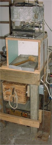
This pot works great, but has a few faults. One of which is that it takes way
too long to heat up for use. Half filled; it takes about 2 hours for the pot to
come up to temperature. And the other point was that it was a loaner from a
friend that I knew he would want it back one day (and he did). That fact, and
along with the other problems I have had with it, I decided to build an
improved (I hope) design.
Here are the materials laid out:
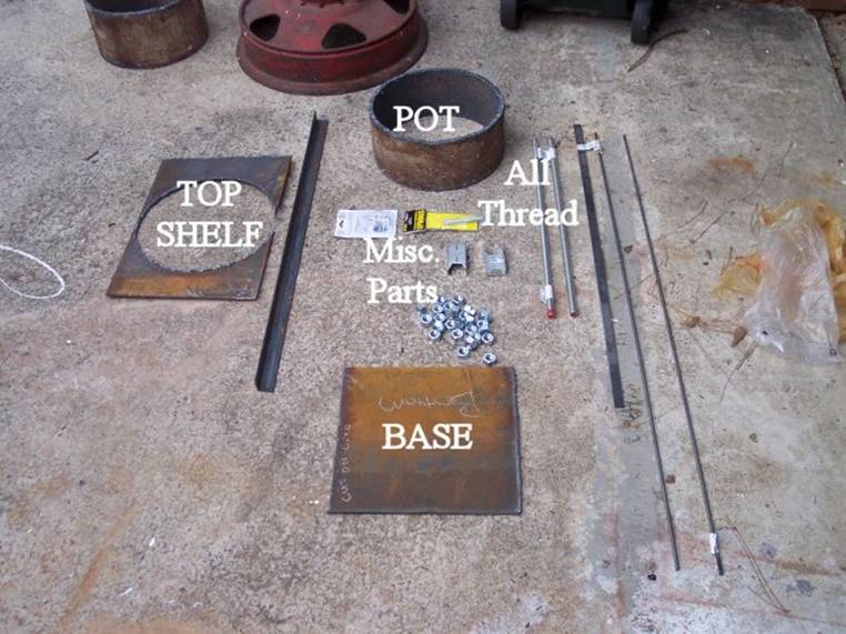
Last week I concentrated on getting all the raw materials. Here is a list of
materials, and their associated cost. I will add more materials as I purchase
them.
$25 - 12" x 12" x 3/8" Steel Pipe Section (I cut this in half
for my pot)
$25 - 13" W x 60" L x 1/4" Steel Plate
$45 - 3 - 6" 1500 Watt Electric Range Elements
$45 - 3 - Maytag Ceramic Element Connectors
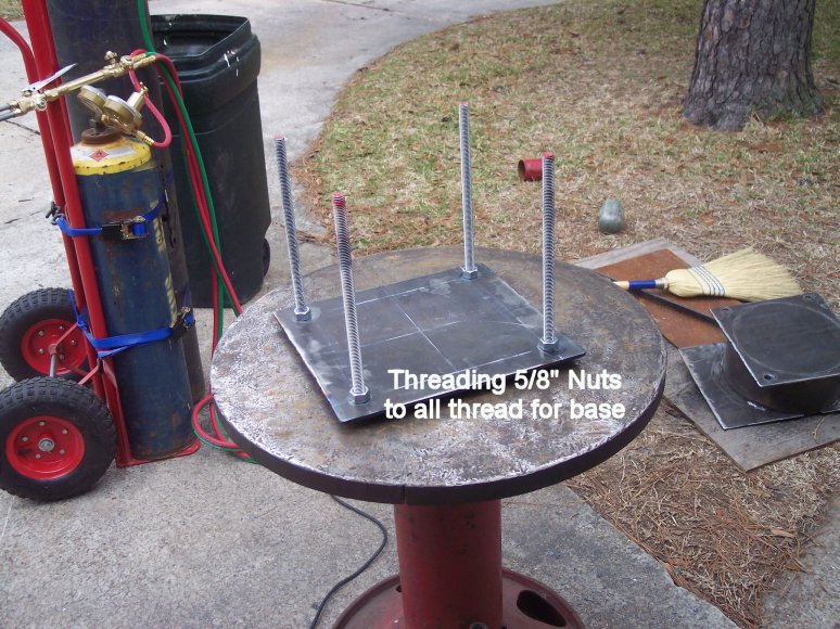
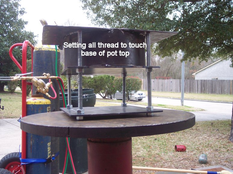
$12 - 2 - 5/8" x 24" All Thread Rod
$11 - 26 - 5/8" Hex Nuts
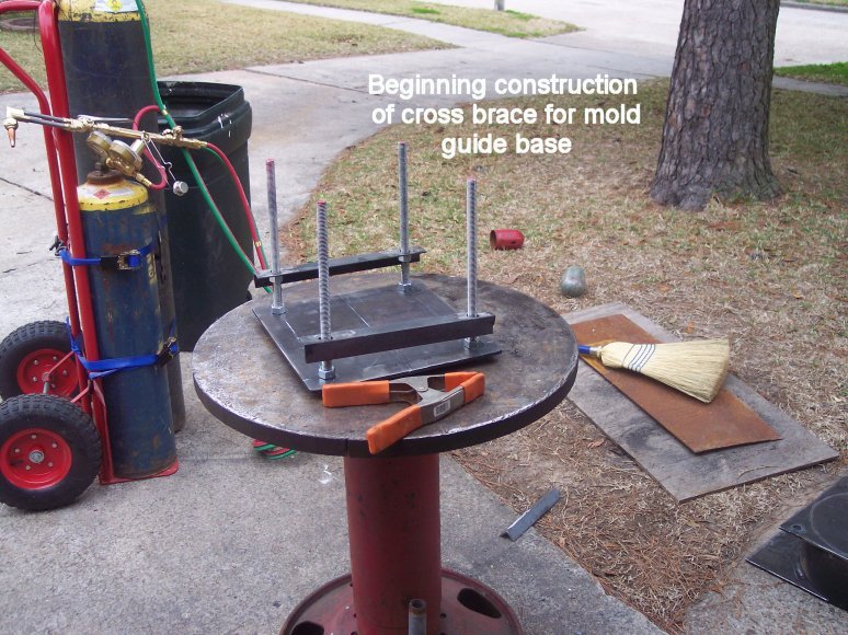
$ 7 - 1 - 3/8" x 24" Angle
Iron
$10 - 1 1 1/2" x 24" Angle Iron
$ 6 - 2 - 3/8" Round Rod
$25 - 1 - 220V Switching Relay (Part of Temperature Control
$32 – 1 used Partlow
Temperature Control (eBay)
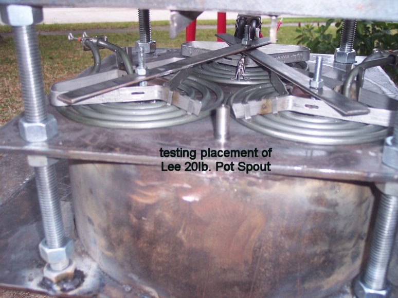
$10 - 3 - LEE 20lb Pot Spouts (I need 3 to ensure spares)
$20 - #10 Electrical Wire
– 10 Feet
$25 – Cutler Hammer 30A Fuse Box
$25 – Misc Small parts (electrical
connectors, grommets, Female connectors, shrink tape, wire wrap)
$10 - 2 - LEE 20lb Pot Spout Rods
$25 – Three
3/8” “Yoke” Connectors
$50 - Consumables (Welding Rods, Grinding Pads, etc...)
___________
$408.00 Total
(approximate cost)
The
tools I used:
Oxygen/Acetylene
Cutting Torch
4 ½” Ryobi
Grinder
220V/50A
Miller Arc Welder
110V/15A
Sears Roebuck Arc Welder
Drill Press
Hand Drill
Tap & Die
Set
Hacksaw
File
Sanding Paper
Dremel Tool (cutting
wheels, sanding wheels, etc…)
Safety
Glasses (Clear, Green Colored for metal cutting, dark arc welding glasses)
Safety
Goggles
Full Face
Safety Shield
Leather apron
for welding
Leather
welding gloves
6013 3/32”
welding rods
6011 1/8”
welding rods
7018 1/8”
welding rods
Pliers
Lockjaw
pliers
Welders chalk
Tape Measure
Metal Square
Starrett Calipers
High Speed
Steel (HSS) drill bits
Wood cutting
band saw or jigsaw
Misc.
Wrenches & Crescent Wrenches
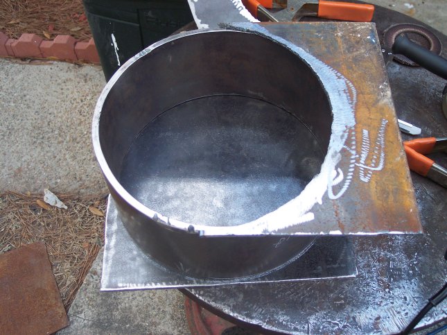
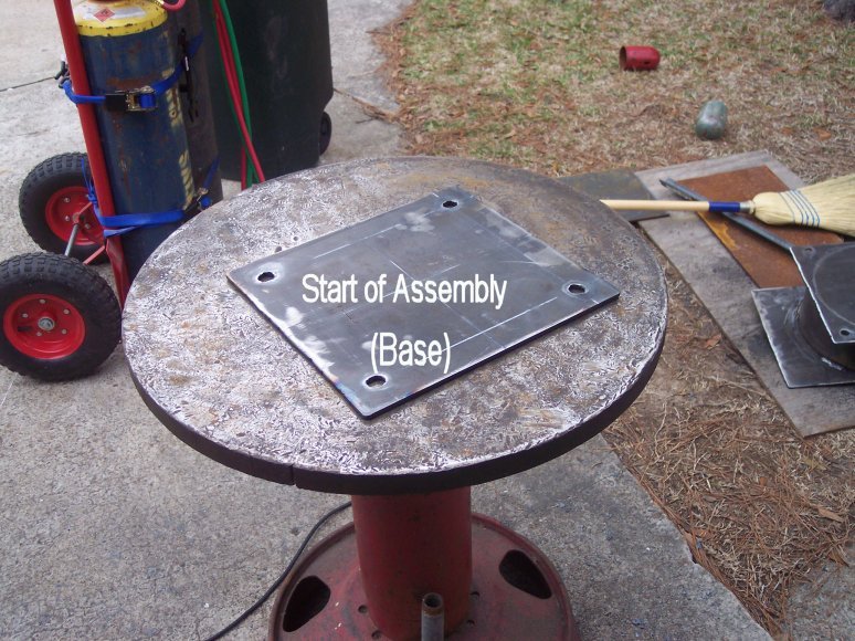
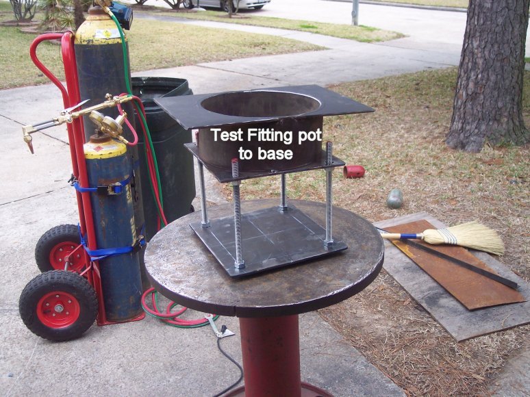
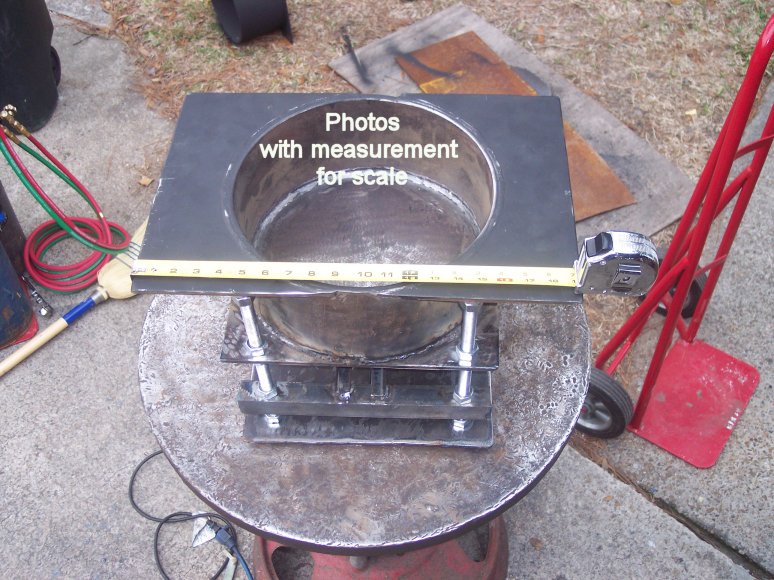
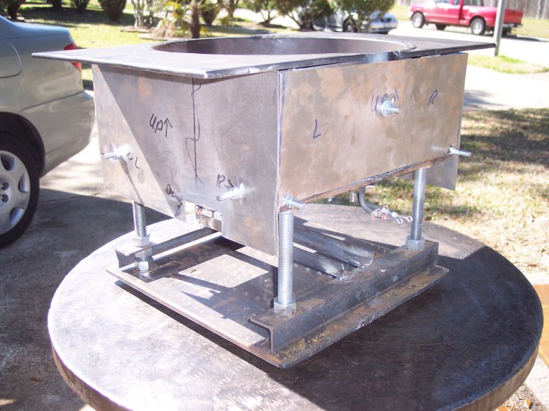
This week I cut the 12" x 12" pipe section in half. My pot
dimensions are 12" Diameter, 5.5" tall, by 3/8" thick. I also
cut the bottom plate and the top shelf plate. This is what they looked like
after grinding all the pieces:
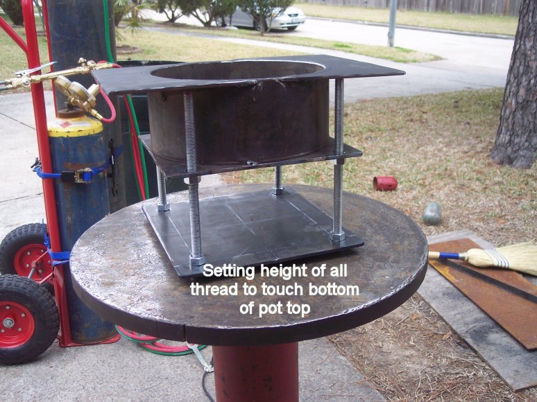
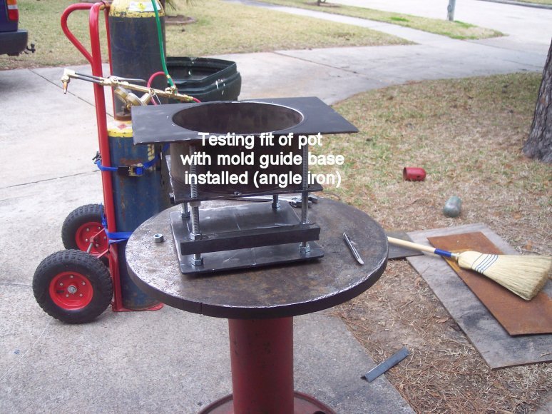
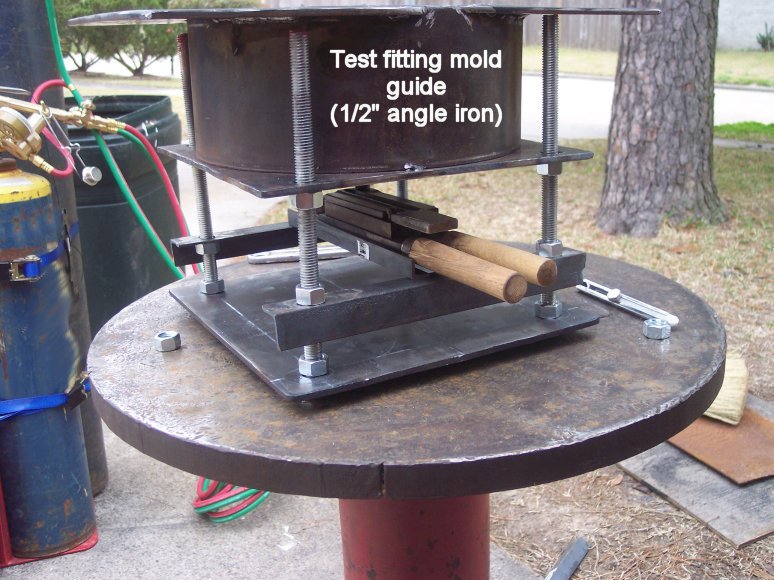
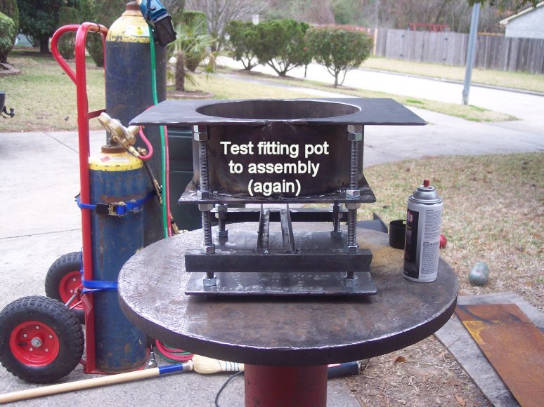
One way of fitting the top shelf
to the pot is to follow these instructions.
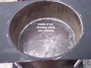
If you notice, the top shelf needs to have its inner curve match that of
the steel pipe for a nice close fit for welding. Since I used an acetylene/oxygen cutting
torch to cut the two pieces for the top shelf, the inside curved edge was
pretty ragged.
The way I fit it was to take the rough
cut inner part and try to scrape it back and forth over the curve of the
pot. Since the outside of the pot was a
little rusty, this “sawing” action, rubbing it back and forth over the pot,
make nice scrapes on the inside curve of the shelf. I simply ground these high spots with a 4 ½”
grinder, and repeated the process over and over until I had a nice close fit as
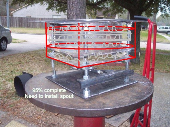
pictured below. Here is a drawing of
what I did to fit that shelf to the pot:
The red spots on the inner curve
represent high spots that would get scratched up from the back and forth
rubbing. Grinding these high spots, and
only these high spots, slowly makes the shelf fit the “curve” of the pot.
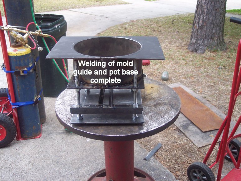
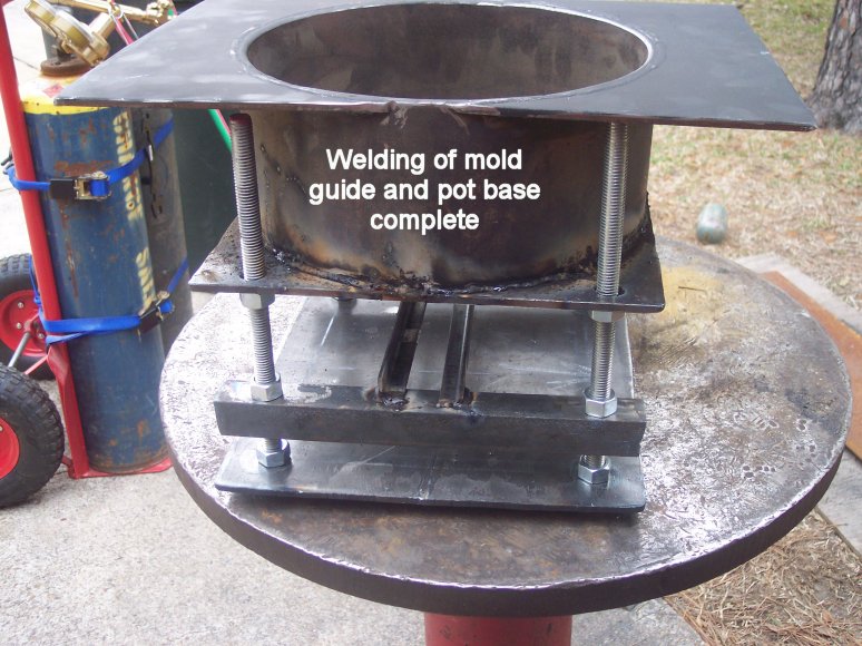
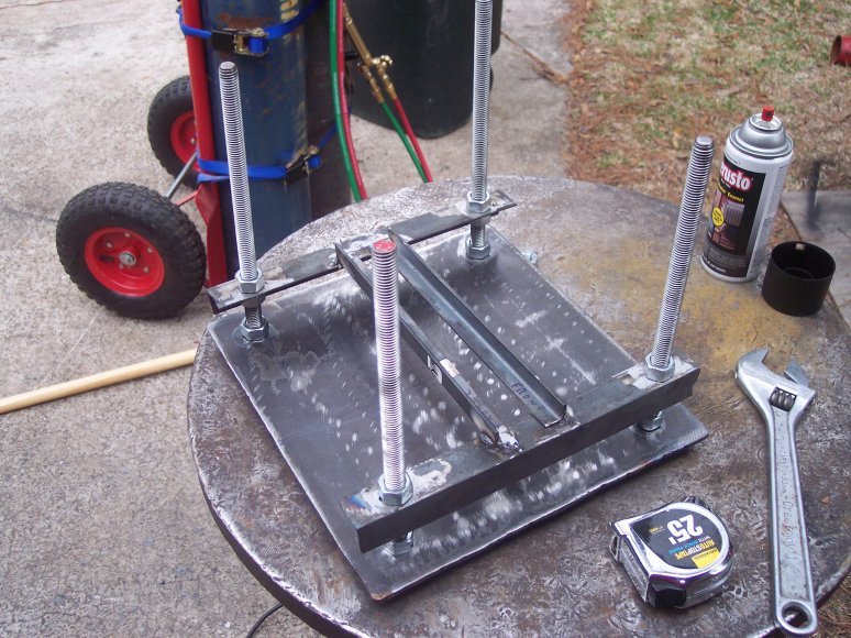
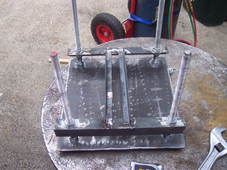
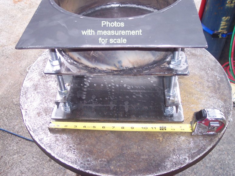
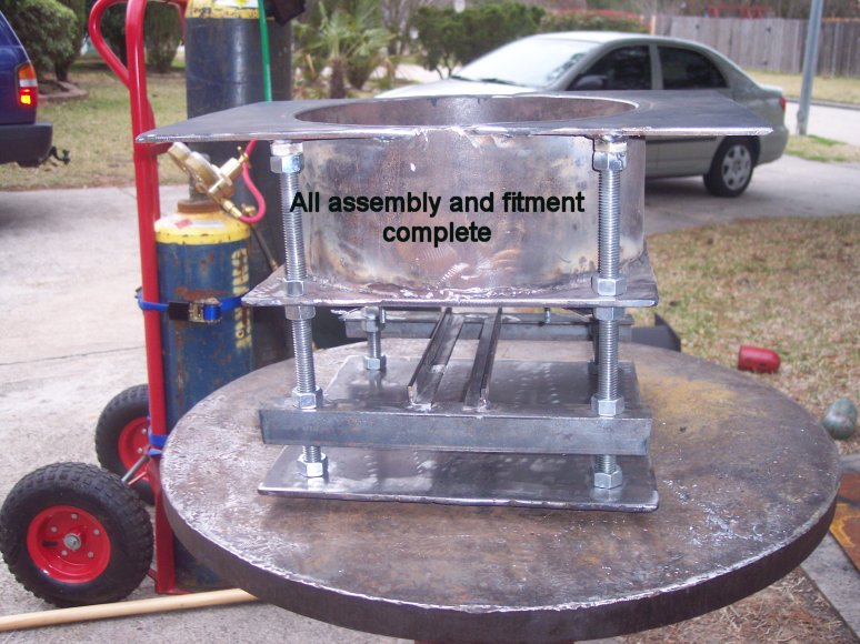
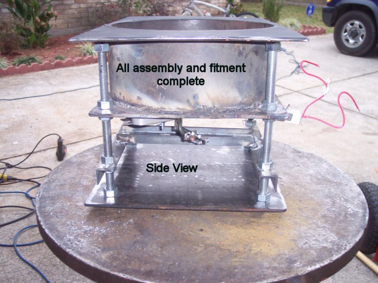
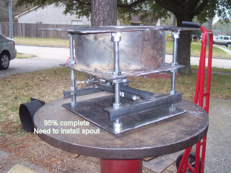
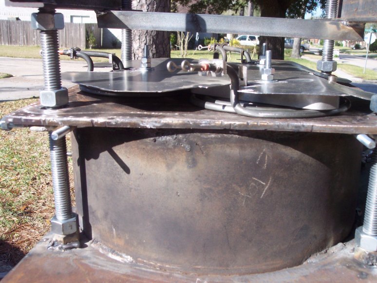
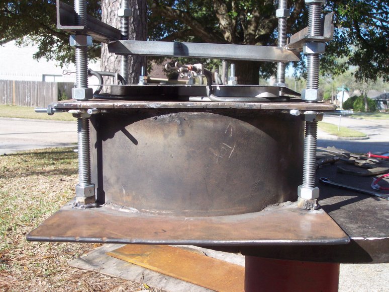
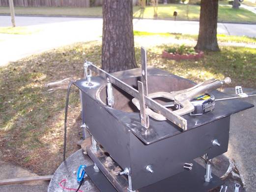
Today I completed tacking the top shelf, the pot, and the bottom plate
together. Here is a photo with a 16oz bottle of coke for scale:
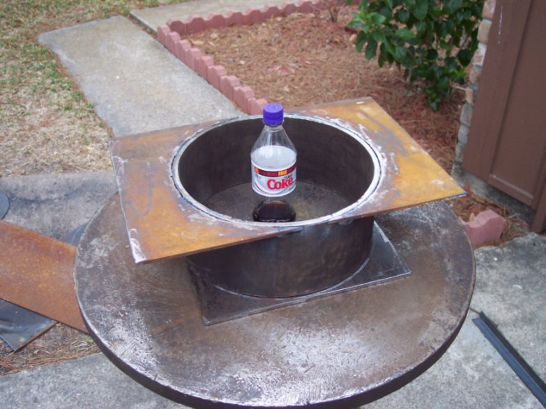
This weekend I expect to do the welding on the pot base, shelf, and anywhere
else it needs.
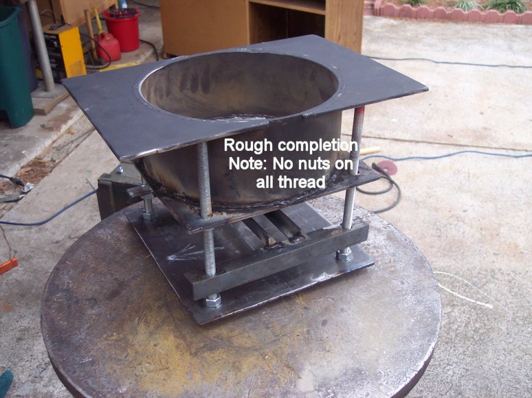
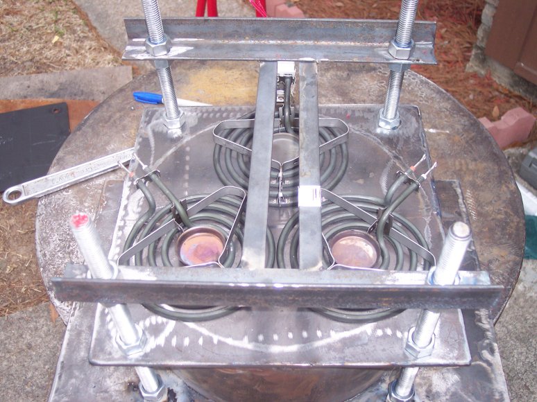
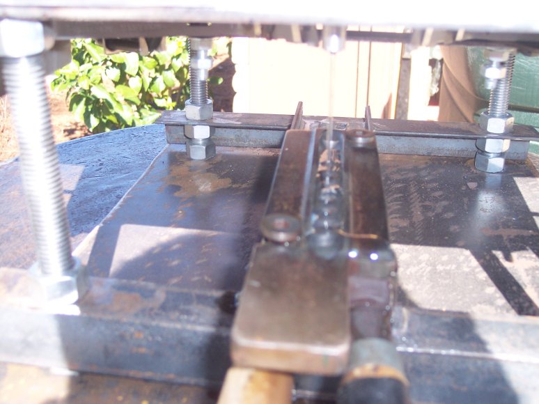
Here is a photo of testing out the element placement:
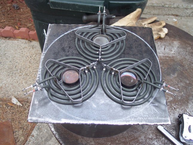
![]()
Here is the result:

I have about 48 photos on my web server showing the progress of construction.
Here are the links to those photos, you can click on each photo for a larger picture:
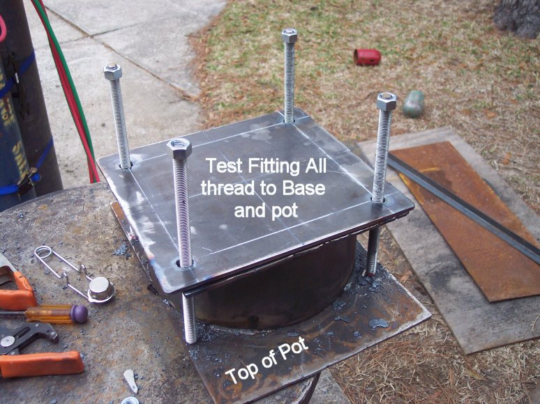


The next step I will drill and tap the spout hole and begin assembly of the
temperature control mechanism which will consist of the following parts:
Partlow 0F to 1000F Temperature control thermostat
220V Switching relay
Individual on/off switches for each heating element [deleted]
On/Off switch for Whole Unit
Small Switchbox with 30A Circuit breaker.
Cord and plug to tap into a 30A dryer outlet
The Pour Spout
After much thought, I decided not to
reinvent the wheel and try and use off the shelf components where I could.
Lee makes some pretty good pots, and I
was able to access their spare parts page online. I noticed that they sold
the 20lb. spout and rod as separate parts. So, I
ordered three of each.
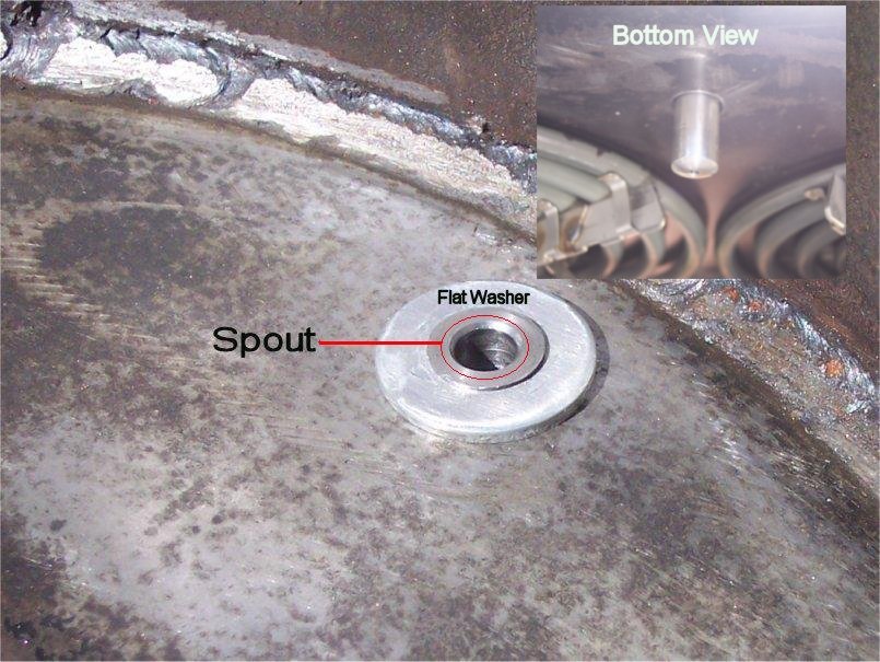
The problem is that Lee only threads
about 1/4 to 3/8" of the spout. To raise the spout off of the pot floor
and create a "ledge" to keep dirt out I used a flat washer bored out
to act as a step. This raised the height of the spout by one washer thickness.
Which, isn't much, but its
better than having the spout level with the floor of the pot. I would use two
washers, but I don't think I will have enough thread left on the spout to
engage.
I was happy with the spout, but disappointed with the rod. The rod looks almost
like an afterthought.
So, time to make my own rod.
Here is the result:
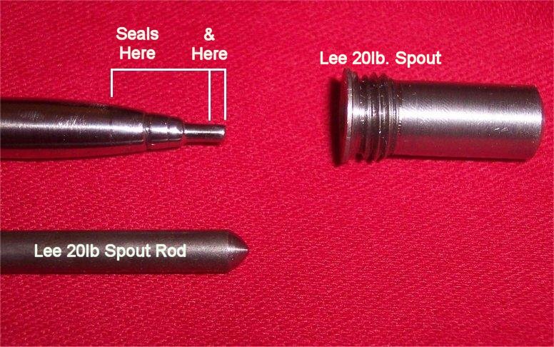
The lee rod is at the bottom (above photo). My new rod is on top. It seals at
both the tip end on also at the flange end. I prototyped the inside of the
spout with a wax cast to see what a rod SHOULD look like.
This is the wax cast:
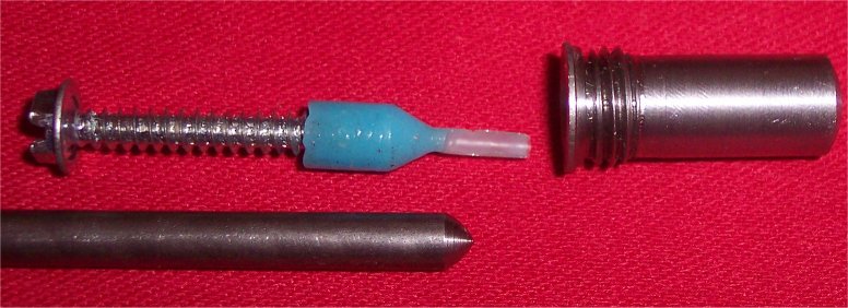
My rod is not nearly what the wax cast is, but patient work on the drill press
with 600 grit sandpaper, a caliper, a Swiss flat needle file, and patience,
patience, patience revealed two sealing surfaces on the new rod. The stock
material (the new rod) was found rolling around the bottom drawer of my tool
box. I think it’s a leftover handle from those kits you buy to take off
bathroom water spigot valves, it’s the handle part. Any good steel round stock would be candidate
material.
The Pour Spout is
continued here
Here is a photo of my current electrical setup. It
uses a 220V switching relay (made in 1962 according to the stamp on the side) its a Partlow
Zero Degrees Farenheit (0F)
to 1000F temperature control, and miscellaneous wiring.
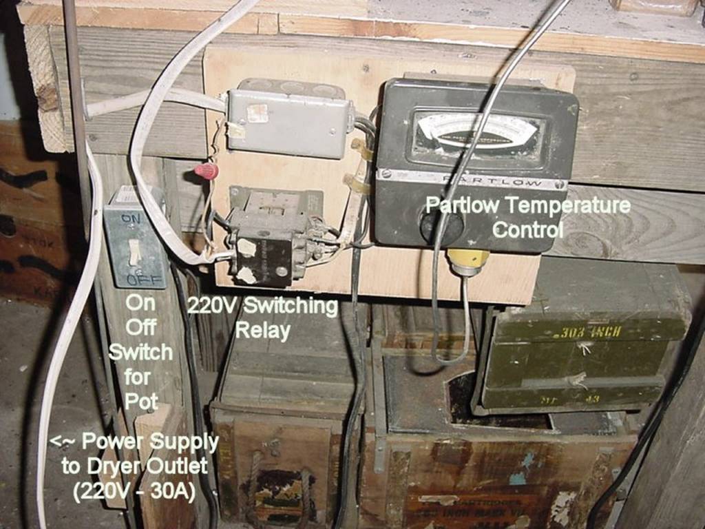
I could use rheostats off of a stove to control temperature, in fact, I was
thinking about that today. That would truly be the low cost option, as the Partlow temperature control is about $250 (ouch!). I
thought that by using a casting thermometer, I could fine tune and calibrate
the rheostats to discover which combination of settings would translate to a
corresponding melt temperature. I
decided that rheostats were a dead end.
I want automatic temperature control.
The Partlow control, pictured above once set up, does
its job, switching the relay on and off to keep the temperature where it needs
to be. The rheostats are an attractive lower cost option, but would always need
to be on. There would be no "off" while casting unless I messed with
them.
Part II
Thanks to a touch of insomnia, I spent the last few hours on eBay and
discovered that temperature controllers can be had pretty inexpensively. I even
found the exact same model as pictured above (the Partlow
MF-4) which is obsolete and discontinued. It sold for $35! So I’ve decided to invest in either a new
temperature controller (called “PID” controllers”) or
find a cheaper alternative in a used unit on eBay.
I emailed one of the temperature control
vendors and for about $75, I can get a modern digital readout, relay output, K
Type (0F to 1250F) Thermocouple Temperature controller. If I go used, the price
drops to about $50. You can also get a
very good new PID controller from Auber Instruments.
With prices like these, I am not using stove rheostats as temperature
controllers. I just may not use the expensive Partlow
temperature controller if I can find a lower cost alternative (I did end up
finding a used solid state controller on eBay, but if I ever have to replace
it, I am going to Auber Instruments and get one of the new digital ones.
Insulation
I had in the back of my mind that I might need to insulate this pot for better
performance. But until a friend raised the issue, the thought never made it to
the surface. Well, it has. I did a little reading on the internet and
discovered Rock
Wool Insulation. It's used in stoves (old and new), blast furnaces,
boilers, etc... The temperature rating appears to be in excess of 1500F. So,
that is what I will use. My plan is simple, I am going to cover the bottom of
the heating elements with a thin plate of steel (1/8", or 3/16th plate) I
will extend that out past the all thread just enough to allow about 1" to
2" of space past the circumference of the pot base. Then, I hope to use
sheet metal to cover the outside of the pot, leaving 1" to 2" of gap
between the sheet metal and the pot wall. I intend to pack this gap with Rock
Wool Insulation.
This is a quickie drawing of what I am contemplating:
That's the plan so far.
I received some advice when I posted about the pot over on Cast Boolits:
|
Originally Posted by powderburnerr You might want to leave a little
air around the elements .I have repaired a lot of stoves that burn off the
connectors when a big pot is set on them they need air circulation...... Dean |
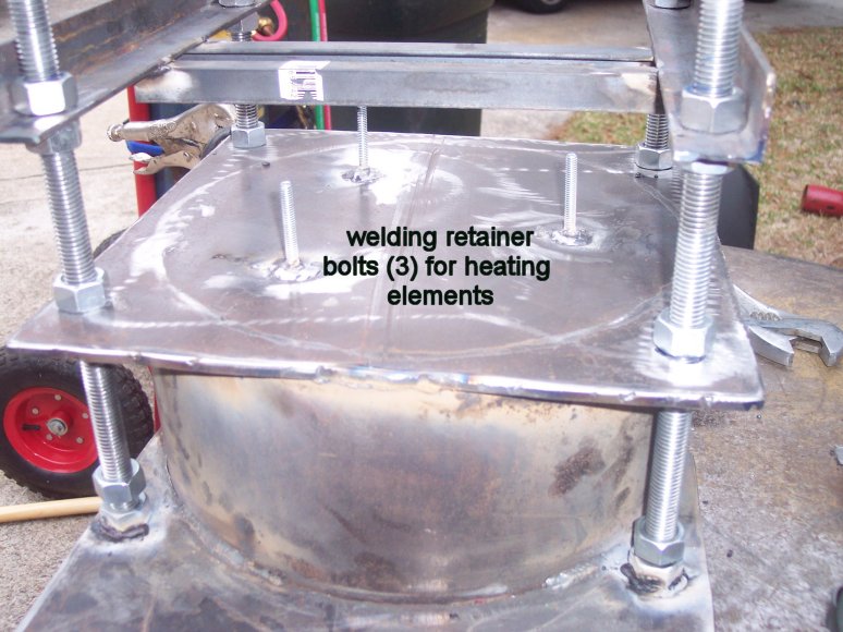
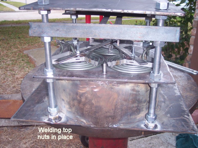
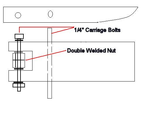
Thanks. This is a quick drawing of what I intend to do with the elements.
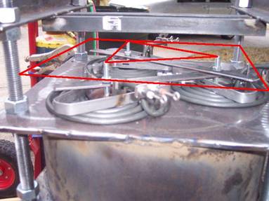
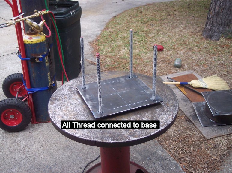
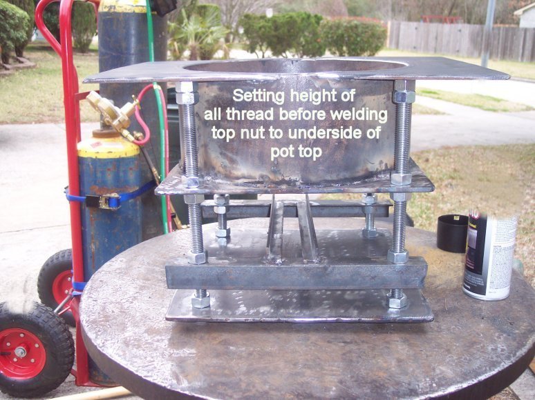
The bolts I welded to the bottom
of the pot to hold the elements in place are long enough to place a double nut
on the end, leaving about 1" of bolt sticking out. I will cut the plate to
fit the red square (from each corner of the all thread) and drill three holes
where the red triangle has corners. I will use that 1" of bolt sticking
out to hold that plate in place. I don't think I will use insulation here, just
the plate cover to block the elements should be sufficient.
This
was a dead end. The bolts and the flat
stock didn’t work. I went in another
direction. See below.
I ended up purchasing a Watlow used solid state PID
controller that was made around 1975. I
found it used on eBay. It had all the
elements I needed in a PID controller.
The heating elements are powered by a 30
amp 240 Volt house circuit that normally provides power to my clothes
dryer. To ensure the power to the pot
was within the range of the 240V/30A circuit, I checked the math.
The formula is:
Watts = Amps x Volts (W = A x V)
Since each of the three heating
elements draws 1500 watts @ 240 volts, we have enough to solve the equation.
1500(3) = A x 240
Solving for A gives: 4500/240 = 18.75 (A)
And the solution to Amps = 18.75
amps.
So the three heating elements
will draw 18.75 amps. I have it on good
authority that you should not run a circuit more that 80% of load. So,
80% x 30A = 24A.
24 amps would be 80% of load, so
at 18.75amps I am under the 80% load limit.
So, power to the three 1500 watts
6 inch coil heat elements is solved. I
can use my 30 amp dryer circuit.
The used Watlow
temperature controller needs 120V power.
Easy enough, as any 120V outlet will do.
No problem there.
The used Watlow
temperature controller has one output that is a relay. The relay simply flips between connectivity
on three contacts. With power off,
contacts 3&4 are closed. A
continuity check verified this. When
120V power is applied to the controller, and (note the “and”) a LOAD is
detected, the relay inside the controller fires and closes contacts 4&5,
leaving 3&4 open.
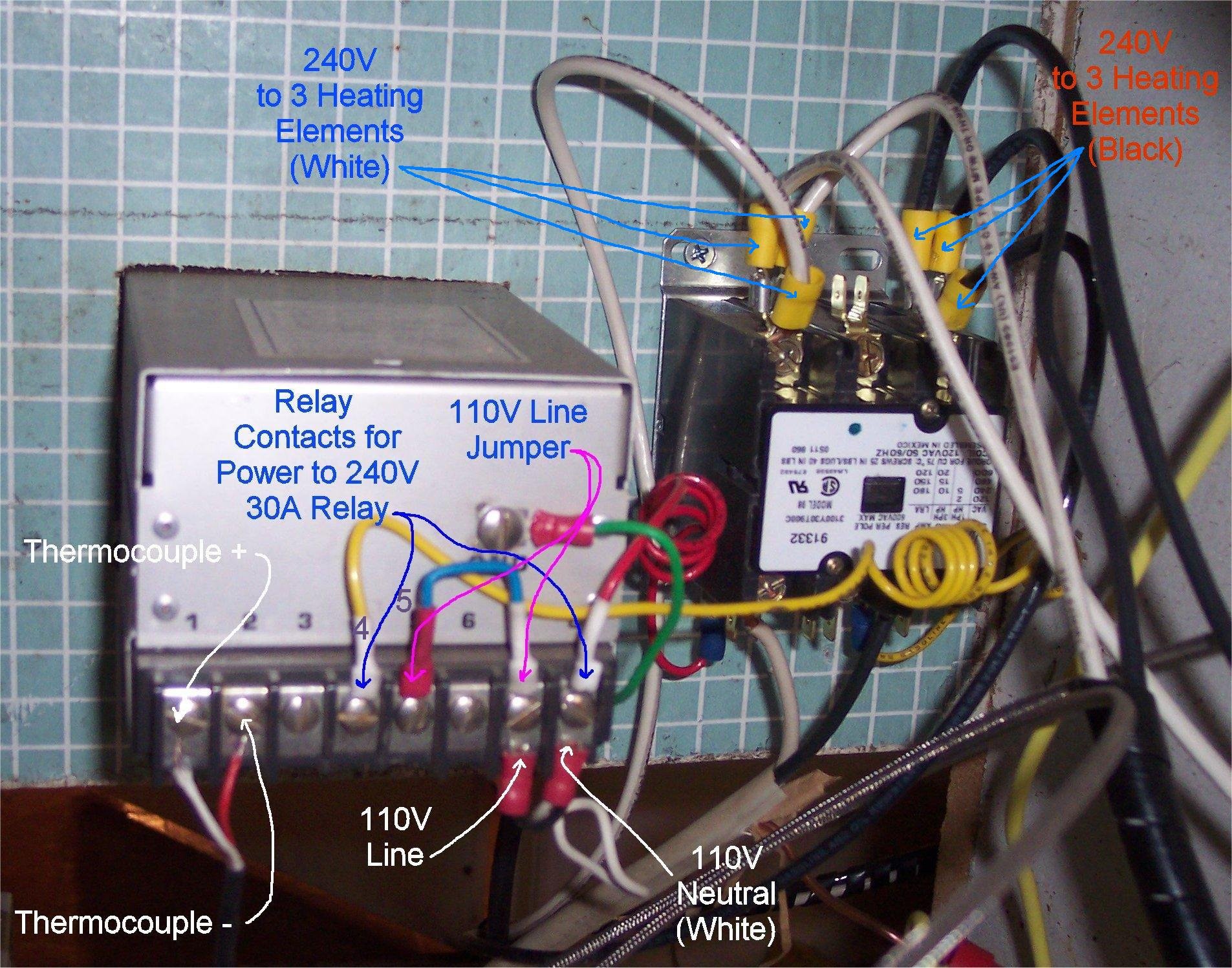
Here is a photo of the rear of
the used Watlow temperature controller. Many modern controllers have a similar
setup. Included also is the 240V 30A
relay that switches power to the heating elements.
Note this is a small photo, click
the following link for a larger easier to see photo:
Note that on my controller, no
power is actually supplied through the relay.
The relay just acts as a switch.
Please note this, as many modern digital controllers also have relay
outputs, but also provide 120V power through the relay (Auber Instruments has many digital PID Controllers that provide this function). This is nice to have. You don’t need to run separate power to the
relay to get 120V power like I had to do on mine. I had to jumper power from contacts 1&2
to get 120V through the relay. I jumpered the “hot” wire on 120V. Not the neutral or the ground. You may not have to do this on a modern
digital relay. All you would have to do
is identify which state the relay contacts are in (open or closed and when) and
run power from those contacts to the big 240V/30A switching relay. Note that the 240V/30A switching relay is
actually powered by a 120V coil, which is how you activate it, and why it needs
120V power to work.
When the 120 Volt coil receives power, it activates, allowing power (in
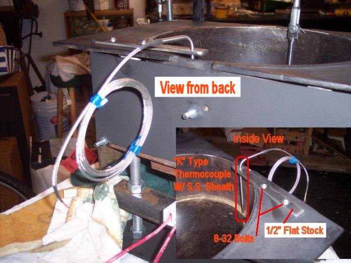
this case 220V) to flow to the heating elements.
To wire the heating elements, I
was careful to observe color coding on the #10 wire to each heating
element. I ran all the “black wires” to
the left heating element connector and all the white wires to the right heating
element connector. I maintained this
wiring coding all the way back through the relay, and through the 30A fuse box,
and through the #10 wire back to the dryer plug. I connected a ground wire to the little “L”
bracket on the rear heating element. If
you notice, on the heating element connectors, there is usually an “L” shaped
piece of steel, very small, about ½” long either side included with the
connector. This little piece of metal is
normally used to attach the heating element connector to the stove or range
top. Where this part connects onto the
heating element is a great place for a ground wire. The other end of this ground wire was
connected to the solid copper ground wire that was on the 240V power on the
powered side of the relay. In other
words, the pot is always grounded before the big 240V/30A relay fires.
A note on the
30A fuse box. This fuse box is nothing more than a Cutler
Hammer 30 amp fuse box that is commonly installed for outside Air Conditioner
compressors. You can use a fusebox, or a little breaker box with a single 30A
breaker. Either will work fine. I used the fuse box because it was easier to
find, and easy to wire.
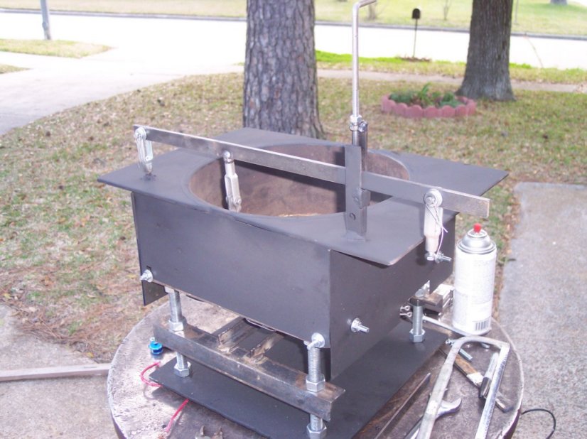
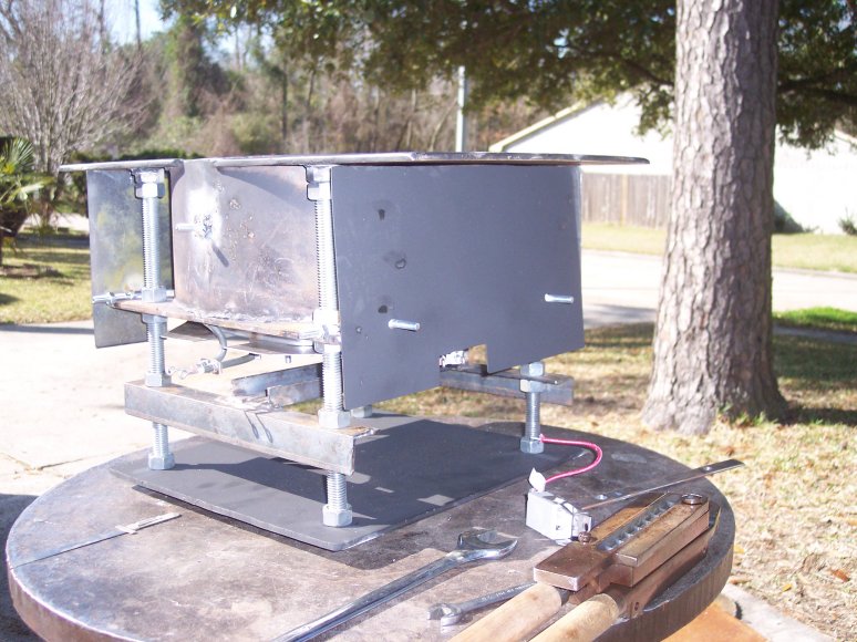
Here is where I am now, shielding has been added to hold the Rock Wool
Insulation:
After Buckshot's post regarding insulation (on the original “Cast Boolits
Thread”), I agreed with his thoughts. It can't hurt, and can only improve
the efficiency of the pot. I was able to adapt the design to install the
shielding, sheet metal purchased from Home Depot and cut to fit.
Drilling and Tapping the Pour
Spout
Prior to the heat shielding, I did finally manage to drill and tap the pot for
the Lee 20lb spout. The Lee Spout is threaded 7/16 - 20. Consulting my tap and
die chart, I discovered I needed a letter size drill ("W") to drill
the hole. Another trip to Grainger, the
only place around I can buy a single letter size drill
bit. This chore took half the day on a Friday. I had to disassemble the whole
assembly to get it down to the pot. I then improvised a platform on my drill
press and clamped the pot in place. From the outside in (meaning I drilled the
pot from the outside of the bottom towards the inside of the pot) I drilled the
hole (using the “W” Drill Bit), and then removed the drill bit without touching
the pot position. I inserted the 7/16 - 20 tap and by releasing the tension on
the drill press, I hand started the tap (Note: No power to the press, I used my
hand to twist the drill chuck manually) with the assistance of the press. I did
it this way to insure a deal straight tap start. Once the tap started, I released
the tap from the press and fitted a hand tap handle and proceeded to tap the
hole manually after that.
I then released the pot, and hand stoned flat the ridge inside the pot created
by the bit coming into the pot. I used a small stone that came with a Buck
Pocketknife. No idea what grit it is (I assume is 100 or 200 grit, give or
take), but I wet the stone, and just patiently worked it back and forth over
the hole until I had a nice shiny flat spot all around the drill hole. I did
the same thing to a flat washer, after boring out the center of the washer to
just under the OD of the spout flange. I finished up both with 600 & 1000
grit wet sandpaper.
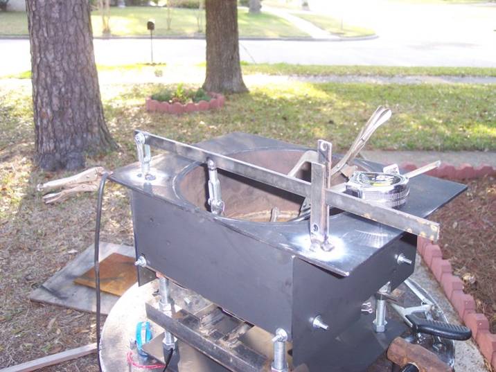
Here is the spout installed:
And the water test to see if the mold guide was centered: (it was)
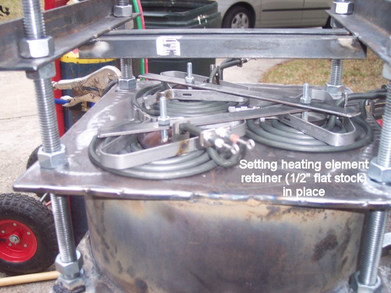
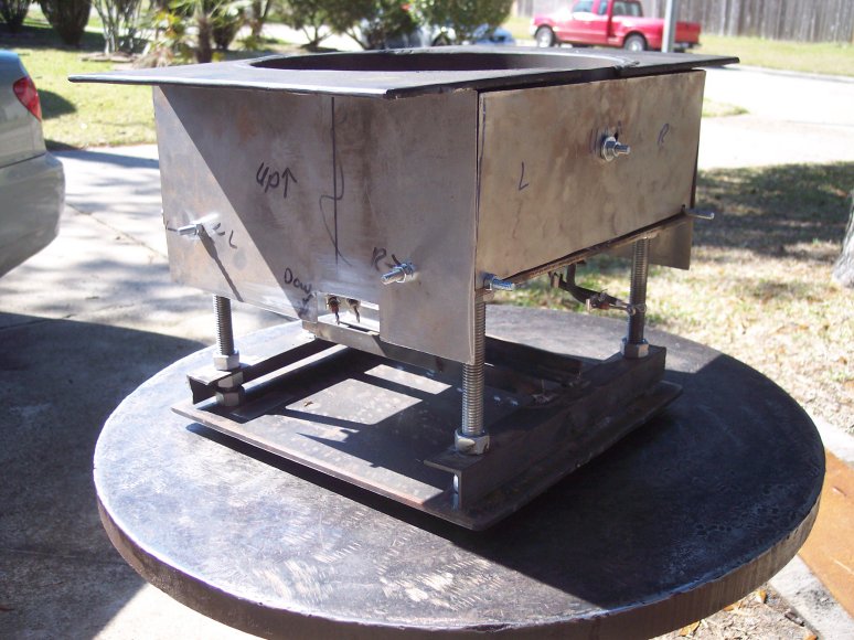
Once the spout and side heat shielding was done, I decided on a design change
for the heating element retainer. Instead of the flat stock (1/2") I had
planned to use, I removed the flat stock and cut to fit a piece of sheet metal
to cover the whole heating assembly, and also to act as a retainer for the
elements. Pictured below:
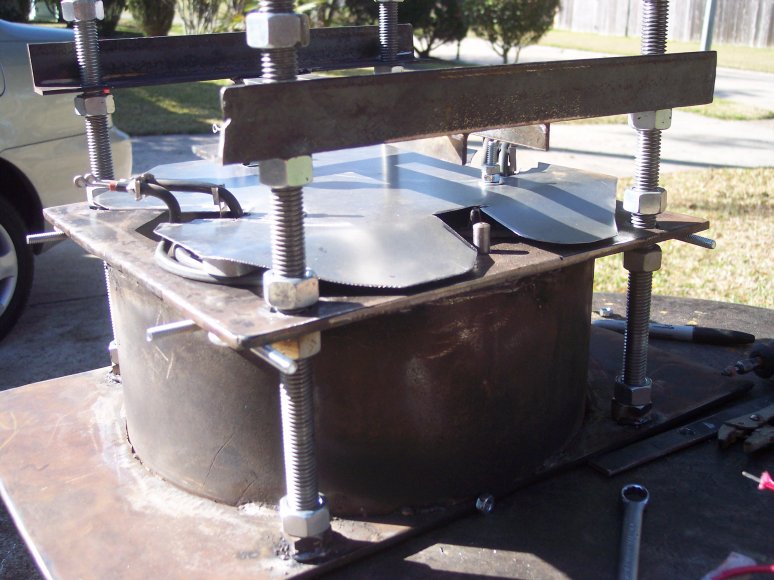
Flat
sheet metal used as heat shield
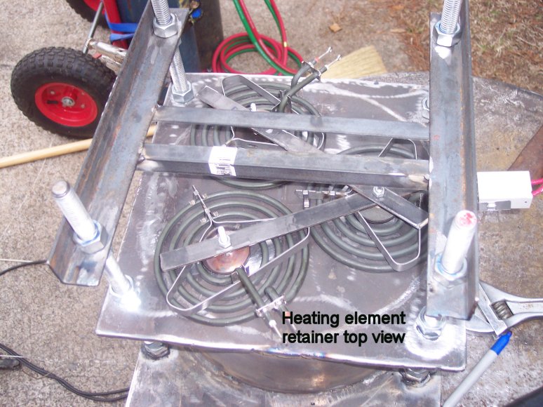
Why did I change this? The 1/2" metal flat stock didn’t' work out because
I had to layer another 1/4" nut on top of the nut holding the flat stock
in place to act as a stop for the heat shield that I was installing. I realized
quickly by the time I layered all those nuts, the mold top would be over
2" - 3" from the bottom of the pot spout, making for a long, long
drop for the lead stream. I was worried that with such a long drop, the lead
stream would cool too quickly and I would get all sorts of problems.
So, after taking a break and thinking about the problem, I realized that the
flat stock holding the elements in place could be eliminated in favor of a
piece of sheet metal to do both jobs, holding the elements in place, and also
shielding the heat of the elements.
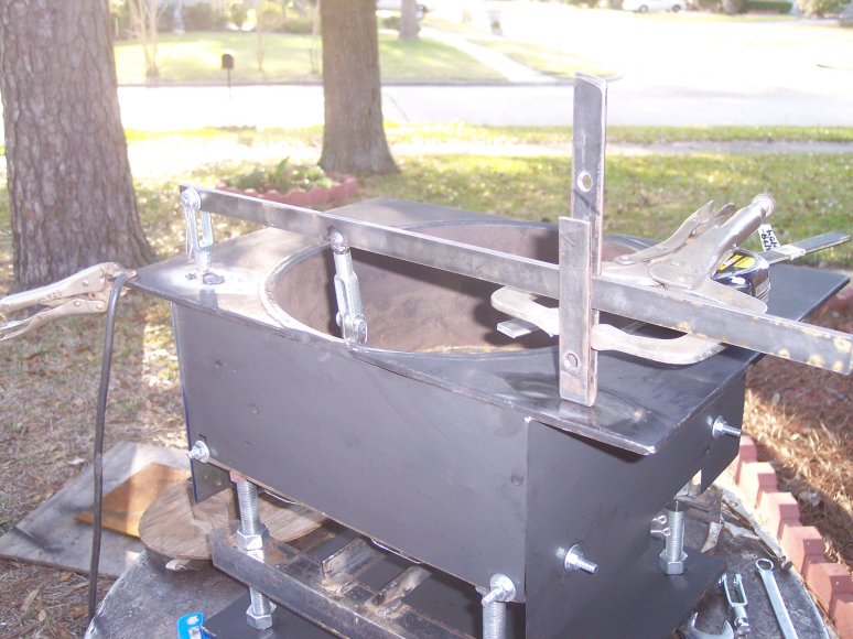
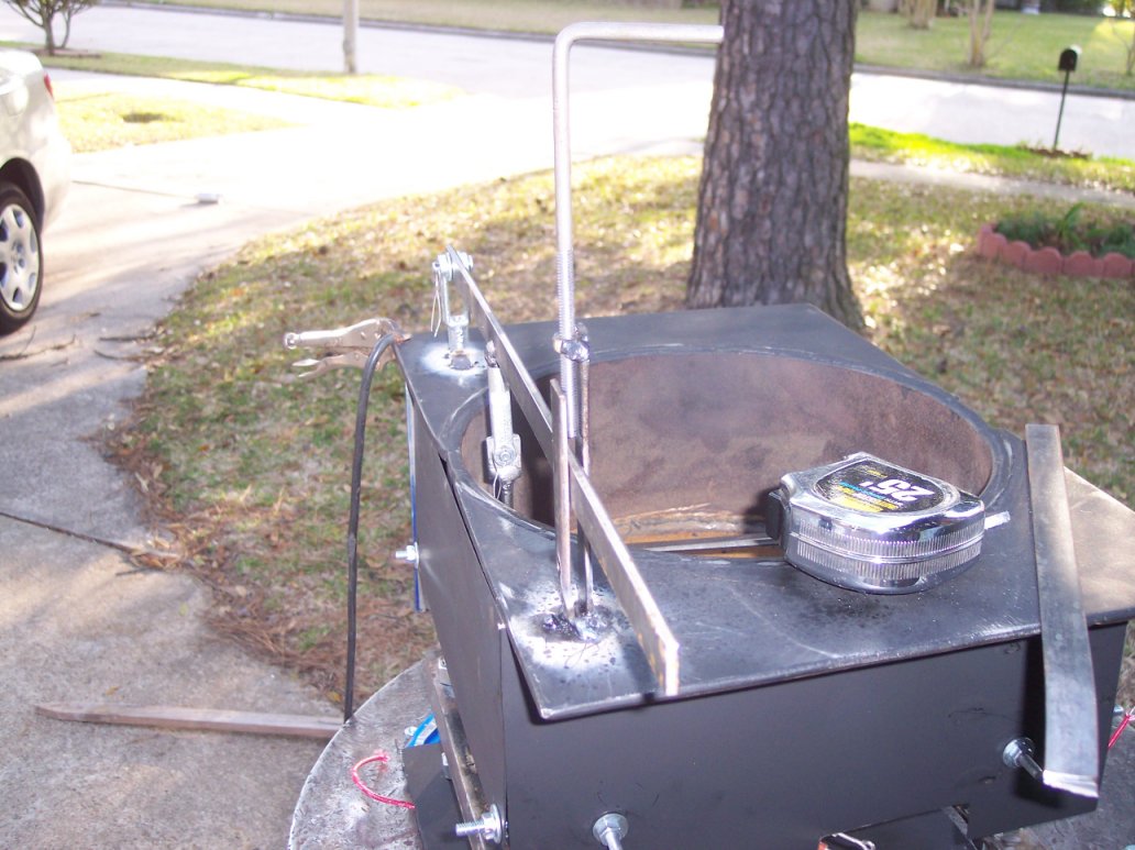
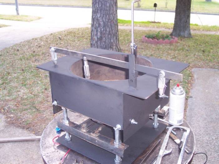
Here is the finished work:

For the remainder of the day I am working on the foot petal activated spout control.
Here is the finished product:
To see the foot pedal spout control in action, click the following link. This
is a a Quicktime Movie
from my Kodak Digital Camera. The file is approximately 5 Megabytes.
Quicktime
Movie of the Spout Control
Here is a URL list of the photos of today's work:


Checking that the Spout is centered
Directly over the center of the mould
guide


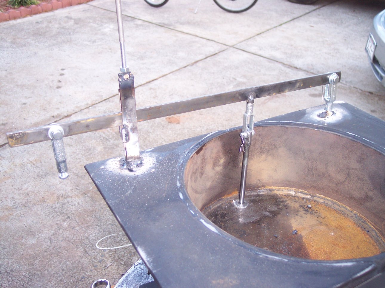
Start the work on the spout/foot pedal
activation
assembly. The throttle
bracket is just resting
on top of the pot at the moment.
I fashioned a foot pedal assembly by
bending flat stock
And “eyeballing” the
design as I progressed.
Using a big “C” clamp to hold the flat
stock in place while
I test the function before tack welding.
Tack welding the support and throttle
clamps in place…
Different view….
Close-up of the welding…
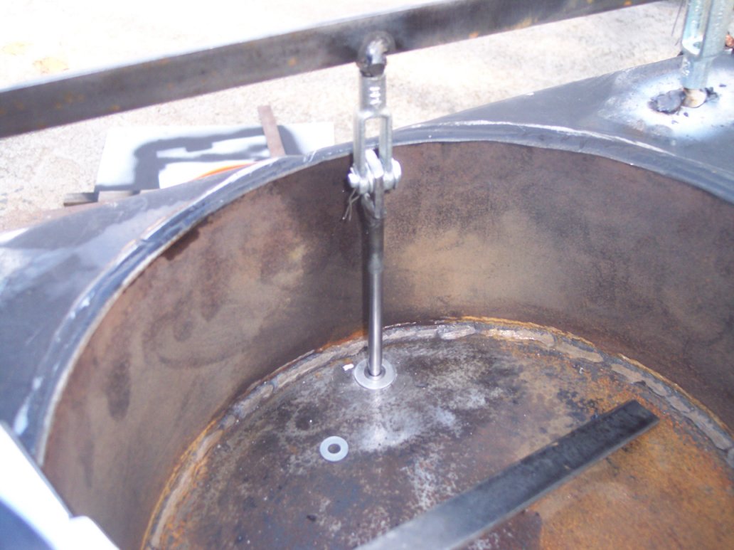
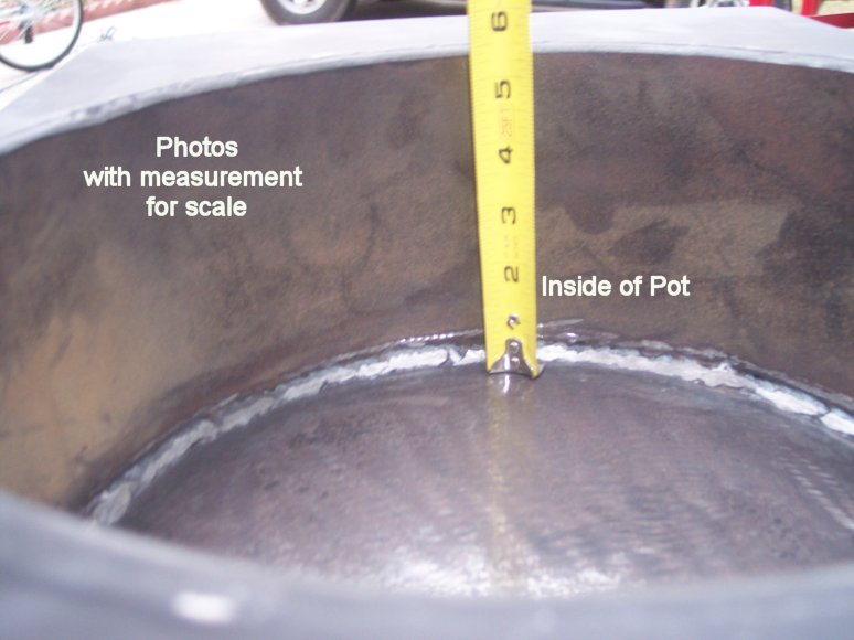
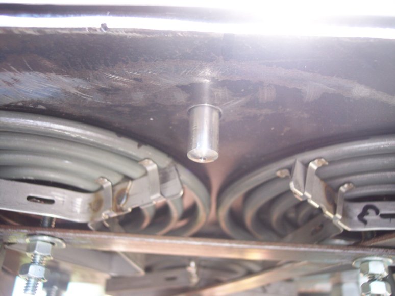
Close-up of the inside of the pot
showing the pour spout, and the “rig” I used
To suspend it to the
foot pedal assembly (the flat stock). Notice how everything
can pivot.
More photos of the welding…
Starting to paint with flat black high
temp paint…
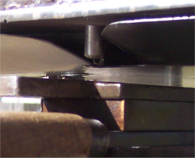
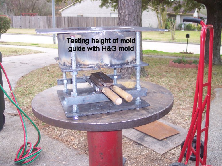
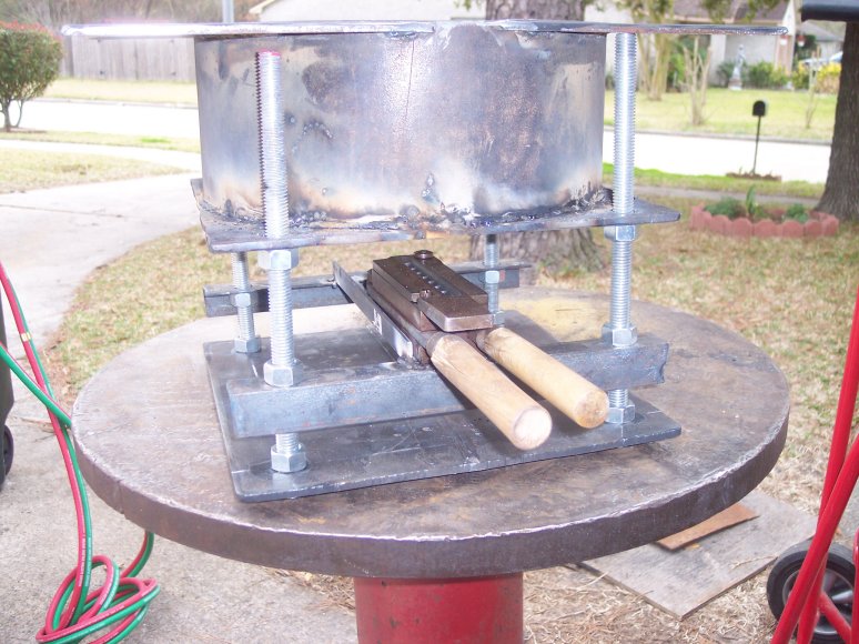
This out of focus photo was a test of
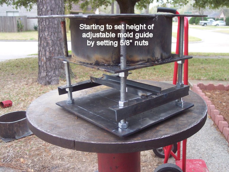
the mould height with a 8 cavity mould.
The washer on top of the mould sprue
stop screw was used to set minimal
Clearance on the mould
guide.
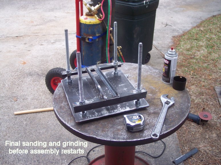
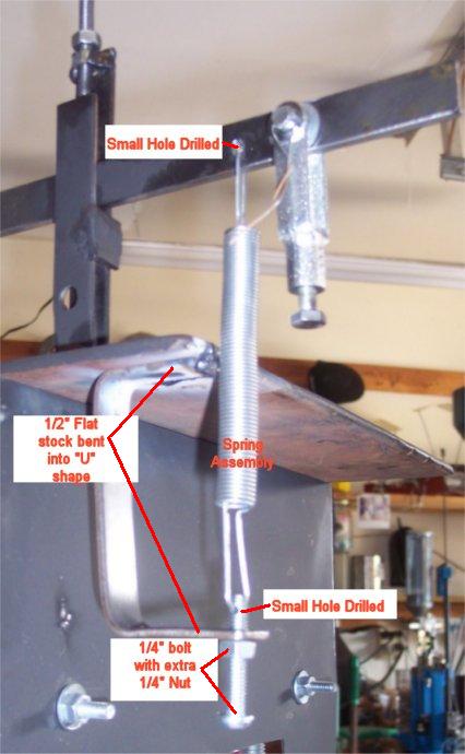
Today’s work was fabricating and
installing the spout lever spring return.
There are photos above and below showing the work. The spout rod needs
opposite force in the form of a spring to ensure that the spout rod positively
returns to the spout hole. I found a spring in the size and shape that I needed
at a local ACE Hardware store in one of those displays that has about 100
different styles of springs on a display board.
I fabricated a little bracket out of leftover 1/2" flat stock with a
hammer and a vice. The bracket was hammered into a large "U" shape
and welded to the underside of the pot top after modifications were complete. I
drilled a hole in the bottom leg of the "U" and tapped it 1/4" -
20. I then found a 1/4" - 20 bolt and ground a little flat side near the
end of the threads and drilled a small hole to accept the spring wire. Since I
was drilling on threads, the flat spot is necessary to get the drill bit
started, otherwise, the bit walked all over the threads. I drilled a small hole
in the 1/2" flat stock foot actuator assembly to accept the other end of
the spring. The 1/4" - 20 bolt will allow me to adjust the spring tension
by screwing the bolt in or out. The extra 1/4" nut will lock the bolt in
place once its set.
Here is the photo of the finished work:
Took about an hour for this part of the job.
Here is the photo of the finished work:
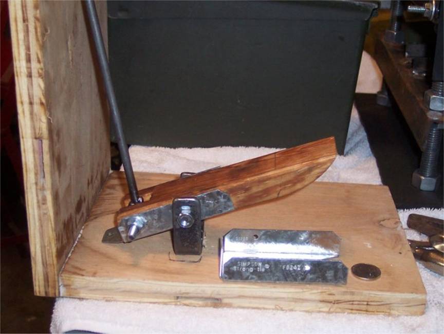
Today
was spent fabricating the foot pedal assembly. I had a hard time with this one,
but in the end it turned out OK.
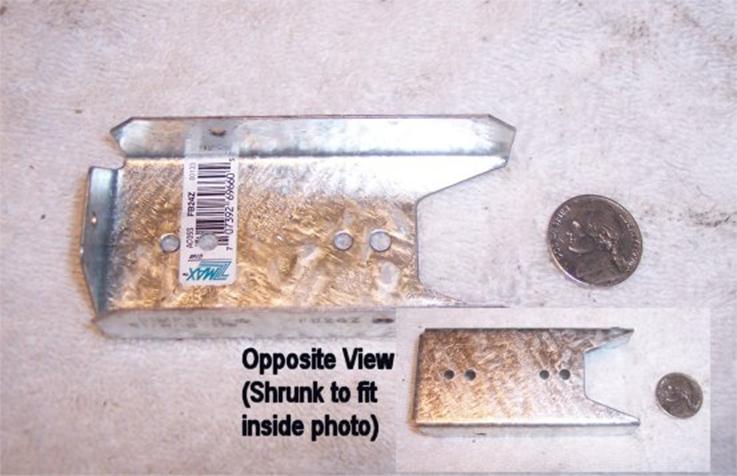
I initially tried to duplicate my old foot pedal, but since it was made
entirely out of iron, and was on the small side, I really wanted to use off the
shelf parts. Problem solved at Home Depot. I found a galvanized reinforcing
sheet metal piece that is used to reinforce deck 2 x 4's. Here is a photo of
the piece, unmodified:
Since it was created to fit over a 2 x 4 (edge on) I slipped it over the edge of
a 2 x 4, traced its outline, and then made a gentle curve from the inside line
out to the edge of the 2 x 4. Something like this:
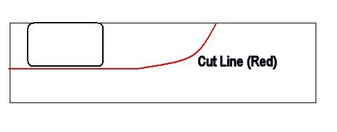
This piece of curved wood would become the foot pedal.
I next took a short (about 8" or so) piece of 1/2" flat stock and
bent it into a wide "U" shape. This would be the bracket to hold the
wood & sheet metal foot pedal to the "L" shaped board (more on
that later).
I notched the opposite end of the wood slice out of the 2 x 4 to create a gap
for a double 1/4" nut that I had welded together (poor man's collar).
Here is a drawing of that:
This was really a one-off, go-by-feel type of thing, so I won't go into more
detail into how I built it. Here is the finished product:
Here is a slightly different angle that shows the "U" shaped bracket
better:
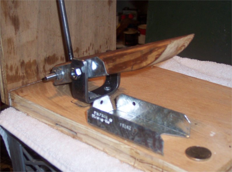
The assembly was bolted to a 7" wide "L" shaped piece of wood as
seen in the above photo. This will get screwed to one of the front legs of the
table where the pot will be placed.
Here is a short Quicktime movie of the foot pedal in
action, it's about 2MB:
Short 2MB movie of the Foot Pedal
The final 5% of work proved to be challenging. Last week I received the Watlow (made in 1979) PID
temperature controller I purchased on eBay. It took a few days for me to figure
it out, and how it worked. I grew to like this temperature control, on the
inside it looks like a High School science project, with relays, resistors, pot
controls, etc... REALLY easy to work and repair these, as you will see later in
this post.
Once I figured out the temperature control, I decided to create a control area
at the rear of the pot to house all the electrics. Here is what I ended up with:
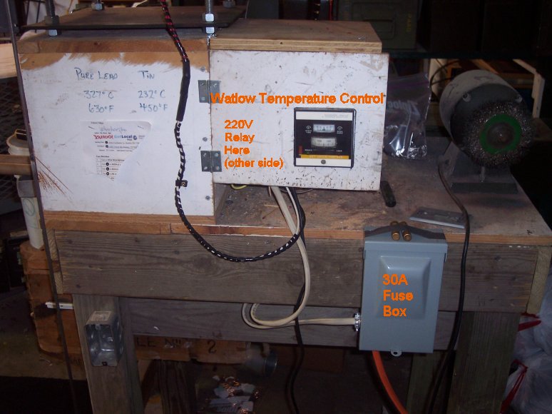
The Watlow is a very simple temperature control. The
dial ranges from 0F to 800F and uses a "J" type thermocouple. There
is a range window above the temperature control wheel that shows action 50F
above and below target temperature range. The relay inside the temperature control
activates when the range setting hits the center. It seems to work pretty well
for a nearly 30 year old control. On this particular model, the relay simply
flips between open and close on three contacts. Contacts 1 & 2 are normally
closed, and when the relay fires, 2 & 3 are closed, 1 & 2 are open. So
I decided to use this relay (inside the temperature controller) to control 110V
to the other 220V 30A relay that I had purchased. It worked fine.
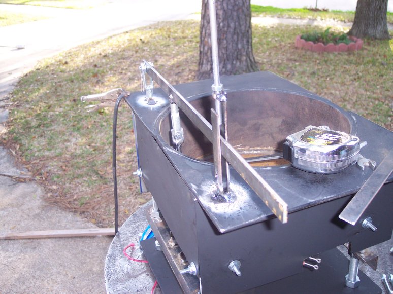
Finishing up the pot called for installing the foot pedal and welding the round
rod to the top of the pot. Here is what it looks like finished (warning - the
link is a BIG photo)
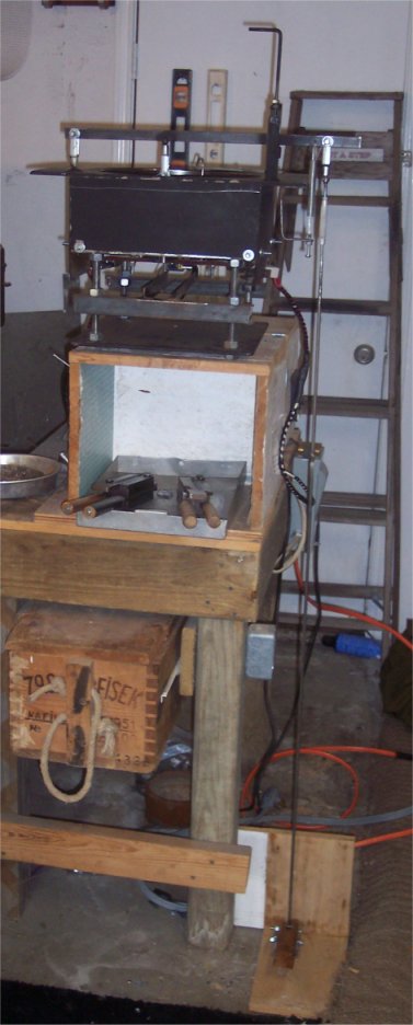
Link
to larger photo
After I finished welding the round rod extension (basically I was connecting
the gap between the round rod from the foot pedal to the round rod that was
hanging from the turnbuckle attached to the spout control) I decided to add
some reinforcing to the wood stand that holds up the pot. Don't have photos of
this, but I had some leftover oak 1" planks and these were cut to fit
alongside the wood box. Once cut, they were gorilla glued and screwed into place
to provide additional support for the pot.
After everything was hooked up and checked for the 10th or 11th time, I decided
to plug it in and see if it worked.
And.........it didn't.
The relay in the temperature control was firing, but the big 220V relay wasn't.
It's not hard to miss as it makes a loud "clunk" when it opens and
closes. I pulled the temperature control apart (the inside just slides right
out of the box) and discovered a broken wire on the relay contact. It was an
old repair, and the wire had been jarred loose. Yah! I got to use my soldering
iron. Popped it back in and the big 220V relay fired right
away.
But, no joy on the heating elements.
I was only getting 110V to the heat elements. Unplugged everything and checked
again. Starting running continuity checks on the wiring and discovered that the
little 30A fuse box I installed had a fuse that was seated cockeyed. The
bracket holding the fuse must have gotten bent (opened up) when I was
installing the box and the fuse wasn't making contact with one of the circuit
legs. Once that was fixed, plugged everything in and .....SMOKE!
Started getting smoke off of everything on the pot.
Residual oil from construction, etc.... Let the temp come up to about 400F or
so and the smoke disappeared.
I didn't melt any lead tonight, just wanted to verify that the pot worked.
Tomorrow, I will start testing the pot with lead to see how long it takes to
melt a 50% load of lead.
I consider the project complete. I want to thank everyone for their
advice and comments as I went along building this project.
Limitation of Liability
You understand and agree that under no situation will we be liable for any
direct, indirect, consequential, incidental, special or exemplary damages for
any use of this site or any linked contents, even if we are advised of the
possibility of such damages. Your only remedy is to discontinue use of this
site. You waive the rights of lawsuit for any damage happened as a result of
the use of this site.
If you
do not agree, please leave this website.
Click here to leave the website
The
activity described below is inherently dangerous. This page described the detailed construction
of a pot for casting with lead, a known carcinogen. Melting lead is an extremely dangerous
activity which may result in bodily harm, up to and including severe burns
and/or death.
This
information is provided without warranty of any kind. No guarantee is made for any of the
information posted.
Use of
this site is at your own risk.
![]()
Back to the
Bullet Casting Central Page